

Everything you need from photometry to the issued report.
Lumadex is a Windows application for lighting design calculations and photometric data. Core road and pedestrian lighting is part of the base application; specialist modules install as add ons.
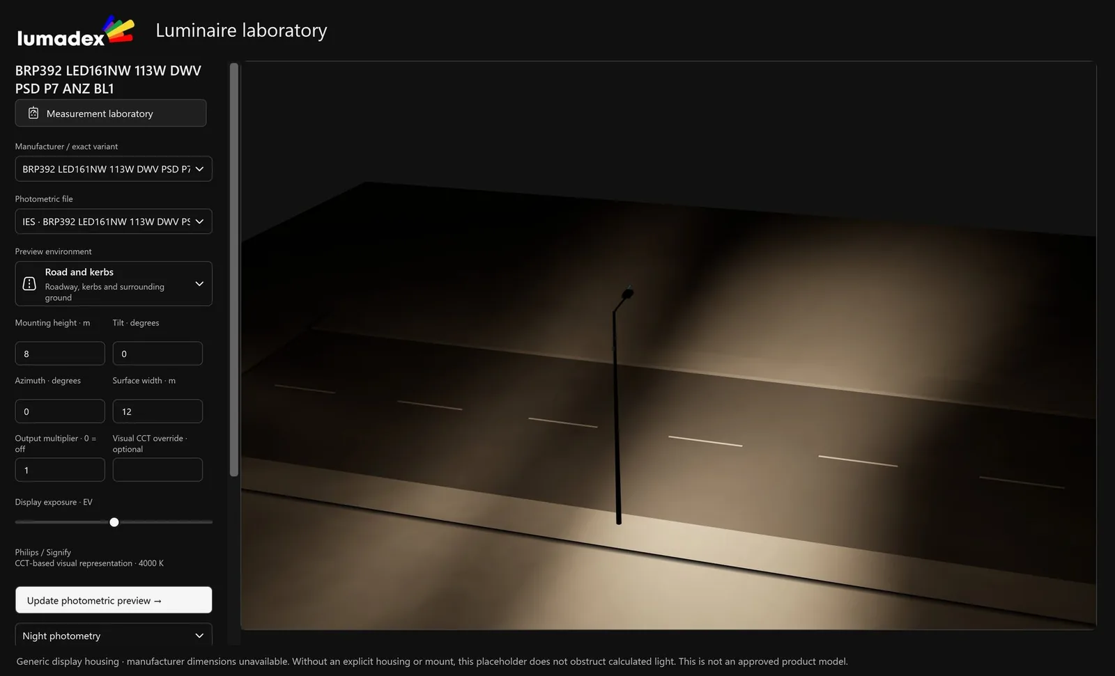
Measured luminaires, turned to face the road.
Each photometric variant is validated and stored with its source evidence. Lumadex reads the asymmetry of every distribution to find its street side, so a luminaire placed on a road always faces the carriageway.
- IES LM 63, EULUMDAT, SAA STAN and IES TM 33 files with validation status
- Street side from the distribution: checked across 51 road files, the derived aim put the most light on the road for 49
- Luminaire laboratory previews each variant lighting a road, wall, room or court before it is placed
- Maintenance factor with its evidence: dirt depreciation, lumen depreciation and the cleaning interval
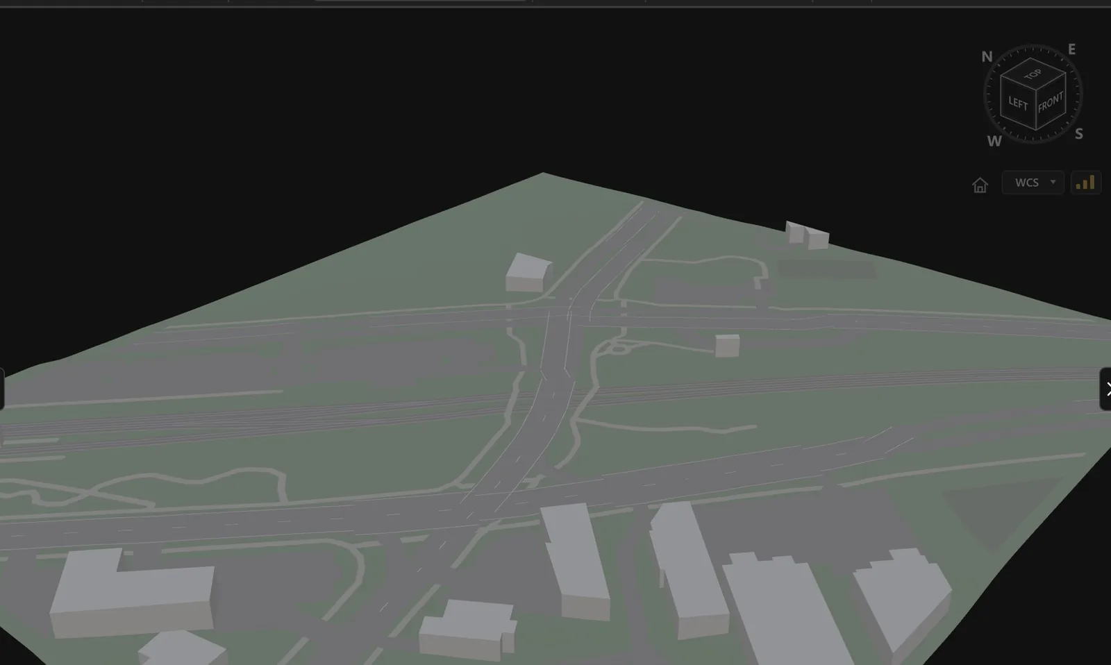
Real ground, roads and buildings in one step.
Draw the site boundary and Lumadex builds the context: LiDAR ground or imported TIN surfaces with aerial imagery, plus roads, rail, paths and buildings from map data. Where the survey is too coarse, a flat or graded design ground merges into it.
- Design ground merged into the survey over a batter, with roads and rail on smooth formations
- Layouts traced over aerial photography at the site's real coordinates
- Drawings aligned to the same coordinates through the CAD Bridge
- Weather, sky and time of day as visual layers that never change a calculated value
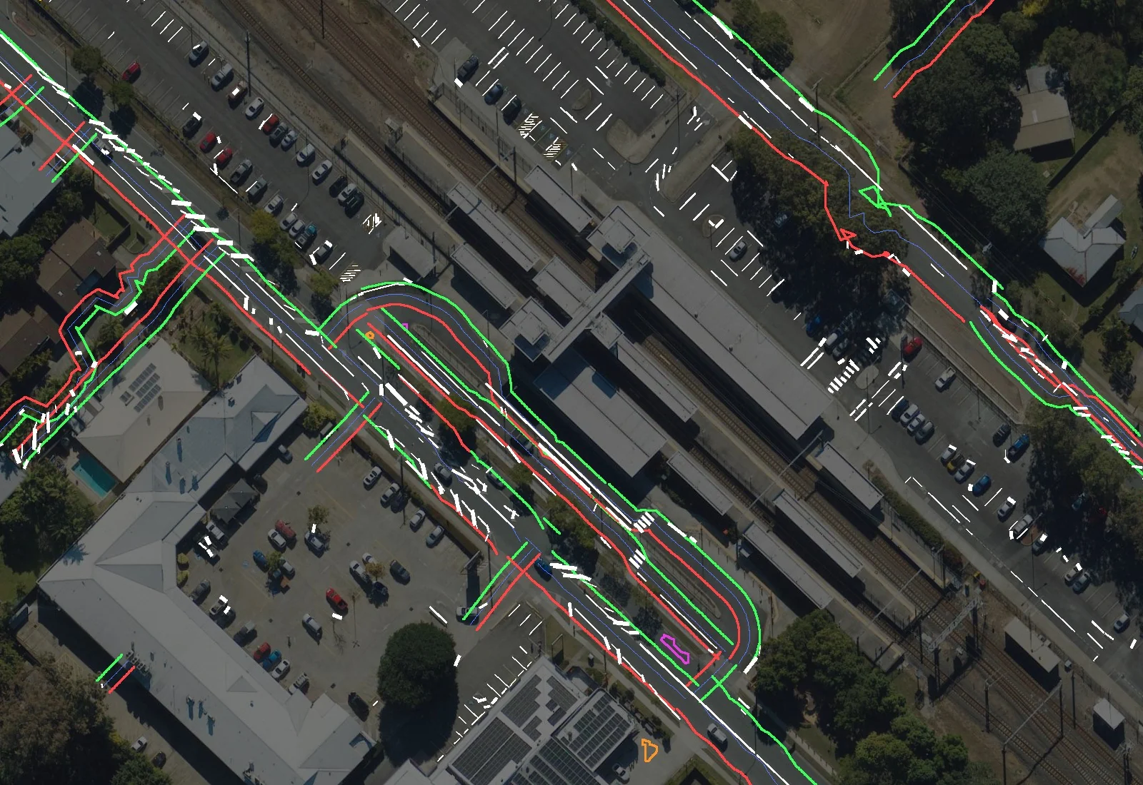
Kerbs and line marking read from the photo.
Site Creator fetches the aerial image of the site at 15 cm a pixel in the drawing's own coordinates. The map is aligned to the image road by road, then each carriageway is measured across at close stations so the model follows the real kerb line.
- Parked cars and tree canopy are stepped over rather than read as kerbs
- Line marking read from the paint: continuous, dashed, crossing and hatching bars in white or yellow
- Sealed ground such as forecourts and driveways added on its own layers
- A creation report that says how much was measured and how much was assumed
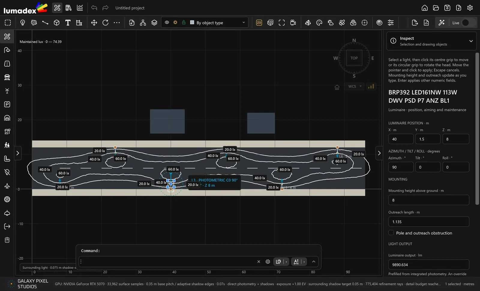
Measured luminaires in a calculated 3D scene.
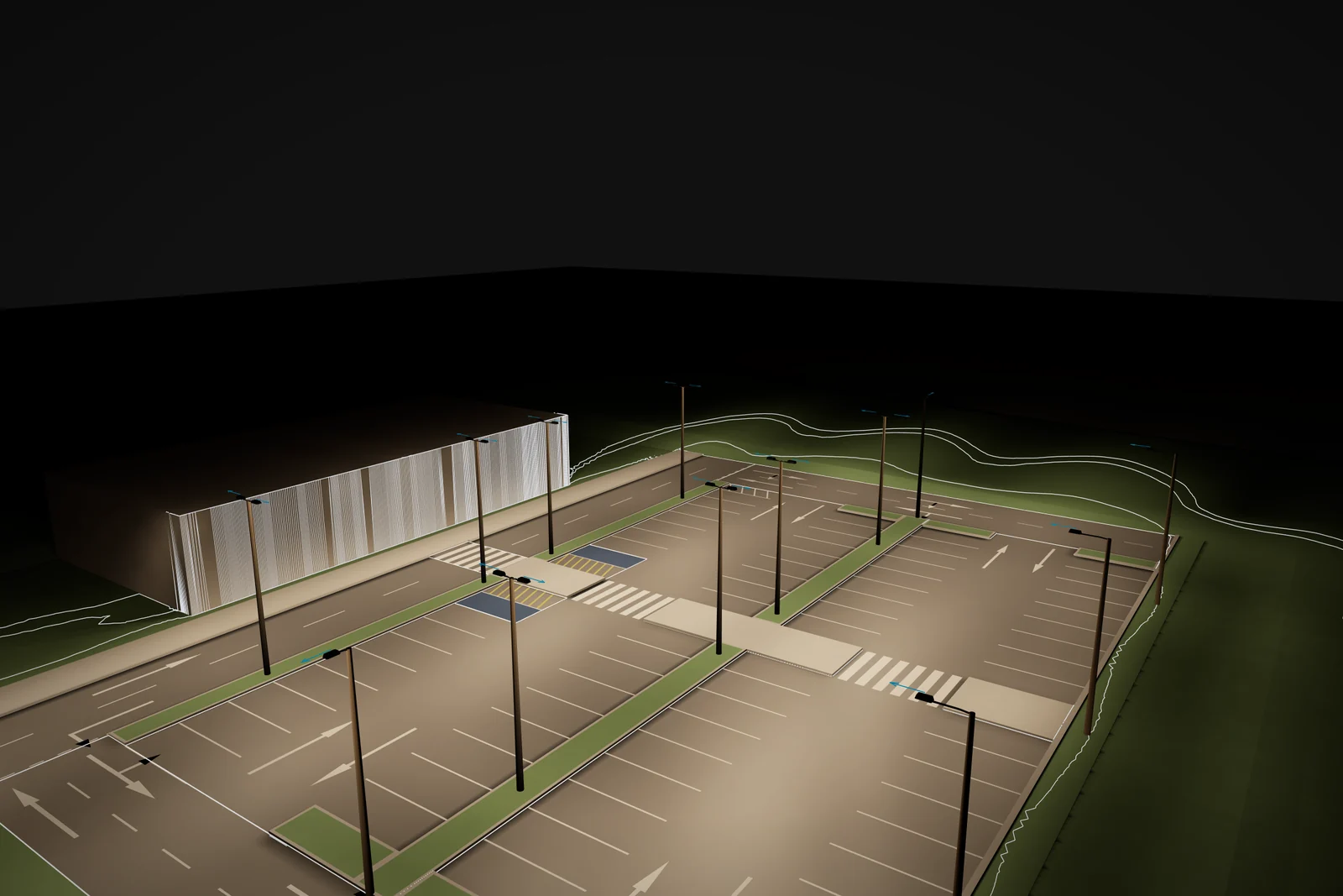
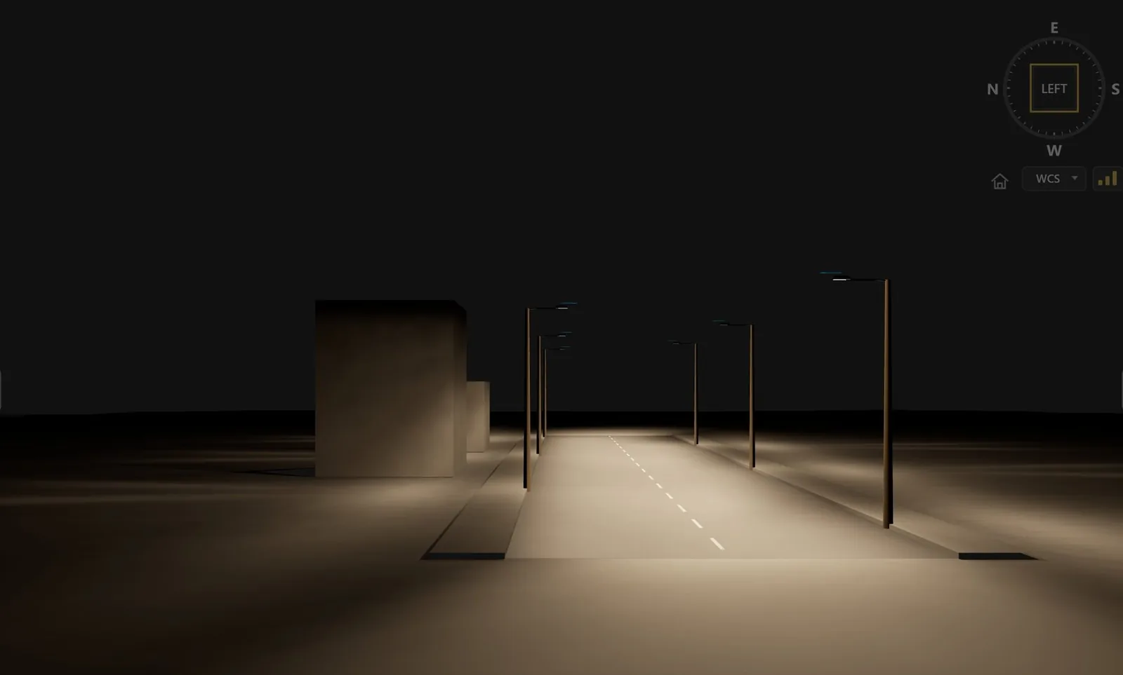
The plan and the 3D view share one model. Poles, outreach and heads are edited directly with grips. The night view is lit on the GPU from the actual intensity tables, with shadows from buildings and poles.
- Live results while a luminaire is dragged or placed, with each area's verdict following it
- Labelled isolux contours in plan and on the calculated surfaces in 3D
- Fly through: a bus into its stop, a car along an aisle, a driver stopped for a train
- Light and dark themes throughout, including the 3D scene and reports
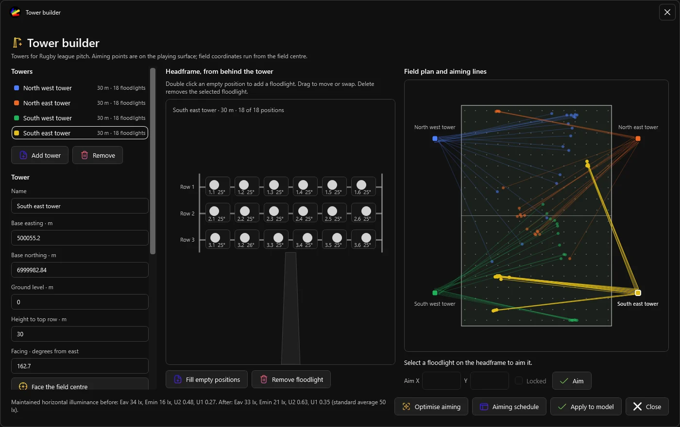
Lay out the towers. Let Lumadex aim them.
The Tower builder in the sports module sets out light towers with their headframes by rows, columns, spacing and standoff. Floodlights come from the library and are aimed by dragging their aiming point across the field plan.
- The aiming optimiser raises the minimum against the average and limits the light spilt off the field, within every tilt limit
- An aiming schedule with tower, position, product, aiming point, tilt and rotation, exported as CSV
- Apply to model draws the columns, headframes and housings into the 3D scene
A photography studio for every design.
Press Ctrl+Shift+P and the viewport becomes a clean stage with no toolbars, grips or cursor. Fly through the model, choose a lens and frame the shot for where it is going.
- Frames for a website hero, card, square, 4:5, story, A3, A4 or a custom size, with composition guides
- What is in the picture: isolux, assessment hatches, imagery, CAD references and labels
- Up to four times supersampled PNG or JPEG, with shots kept in the project
Let Lumadex find the layout.
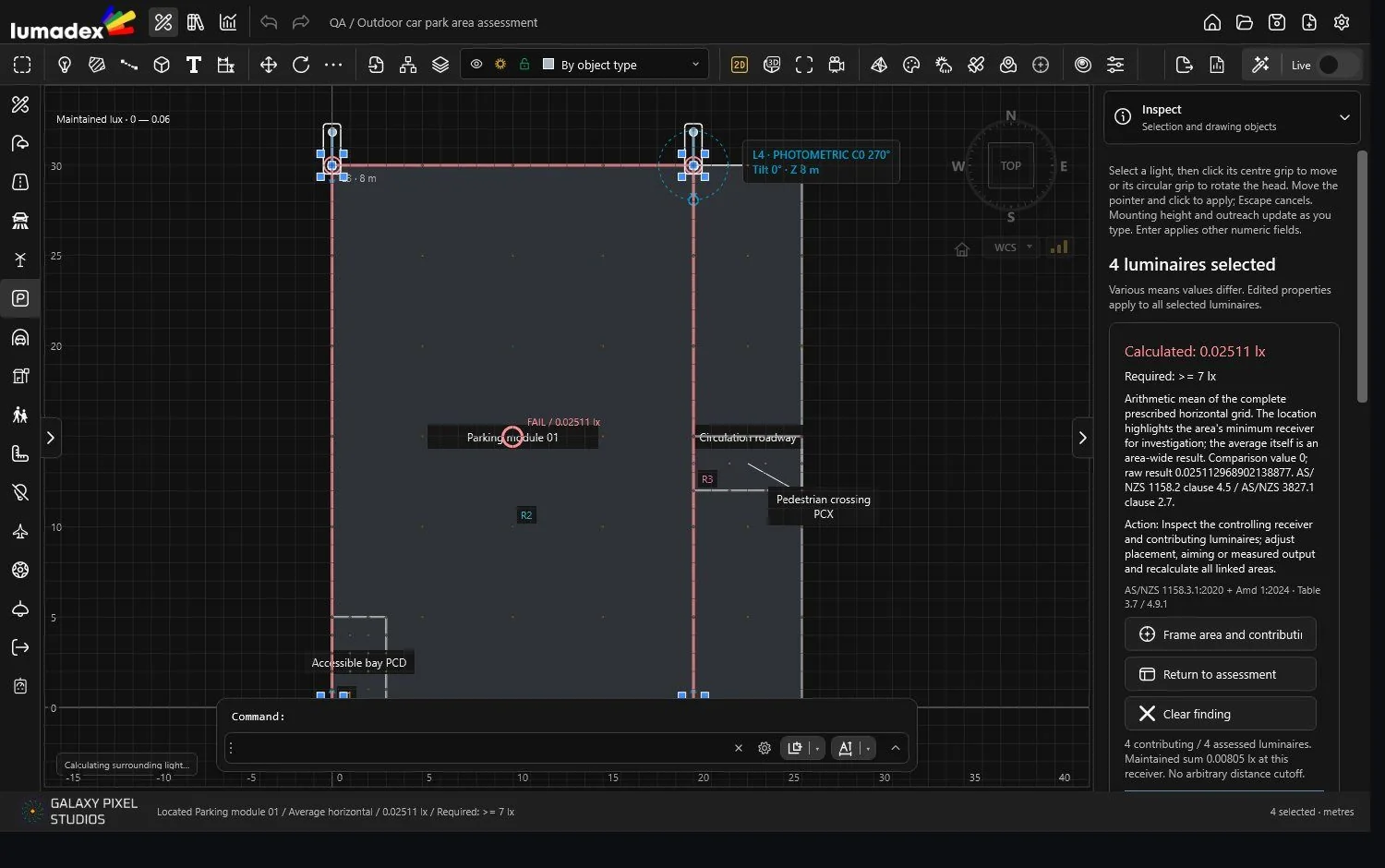
Draw a hatched Auto Calculation area around the poles that may move. Auto Calculate moves, turns and tilts them inside the area to best meet every assessment target, keeps the whole pole base inside and never makes a design worse.
- Explicit links: you choose which luminaires each area may move
- Spacing respected: every spacing run and calculated scheme stays within its maximum spacing
- Before and after for every area, pole and run, with one undo to restore the layout
- Area colours: hazard tape by default, any preset or your own saved colours
Spacing tables and spacing runs.
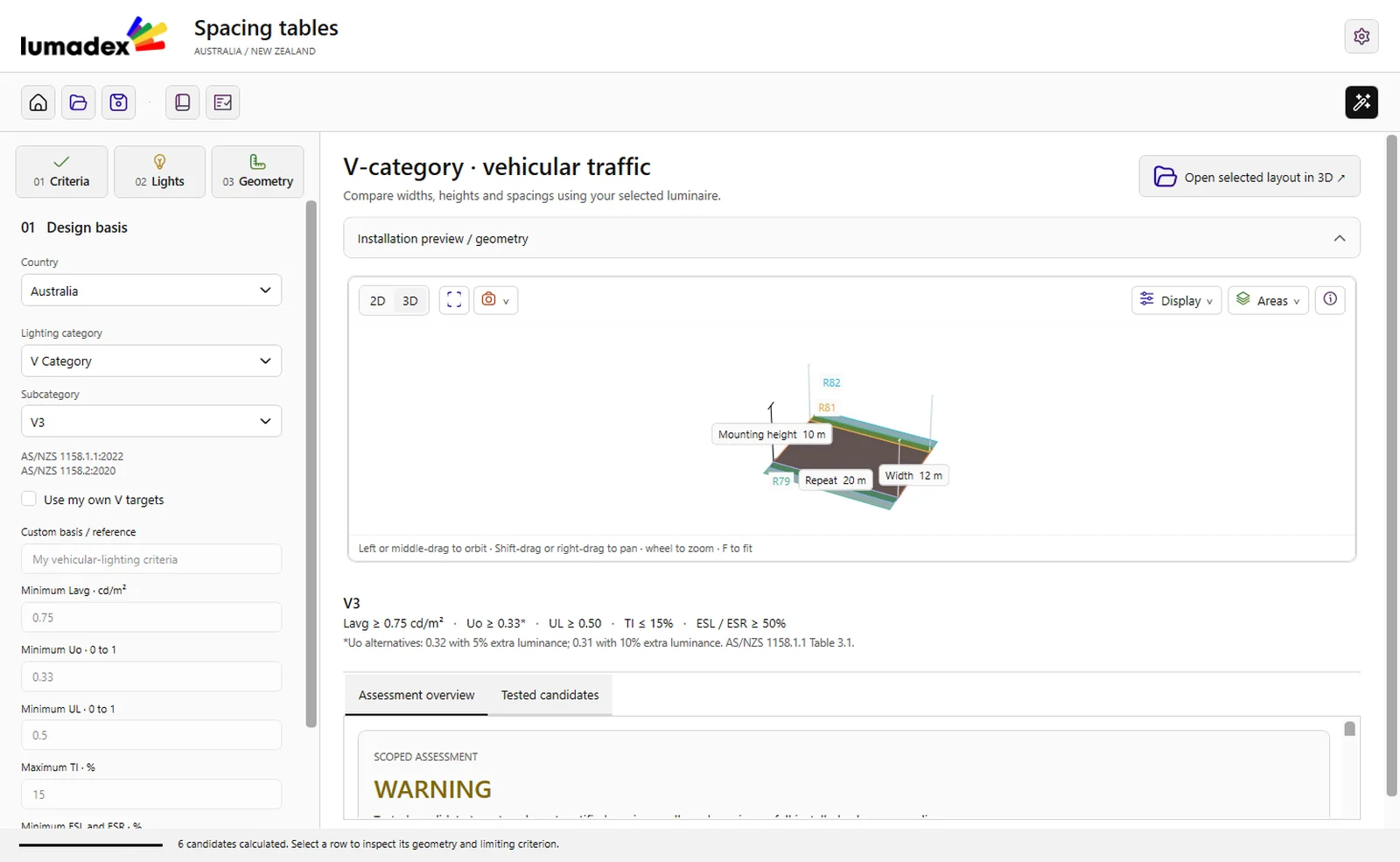
Spacing studies search pole spacing, mounting height and outreach for a chosen luminaire and report the largest arrangement that meets every criterion. Spacing runs then check every span of a layout against S as you design.
- V category luminance, Uo, UL, TI and SR with the SAA STAN method from the luminaire's own photometry
- P category tables with average, minimum, vertical and surround illuminance for every tested spacing
- Into the model in one step: a passing row is placed as poles
- Spacing runs coloured within S or over
Assessment reports ready to issue.
Each module writes a PDF that records the inputs, the photometry with its hash and the calculation method. Every criterion is listed with its clause, required value, calculated value and controlling location.
- Failed and open criteria first, grouped where they share a requirement and result
- Area sheets with false colour, labelled isolux, every calculation point and the criteria for the area
- Calculated values laid out as they sit on the ground
- Captured views framed on the luminaires and receivers
- Certificates of compliance for areas, maximum spacing and flag and hazard lighting
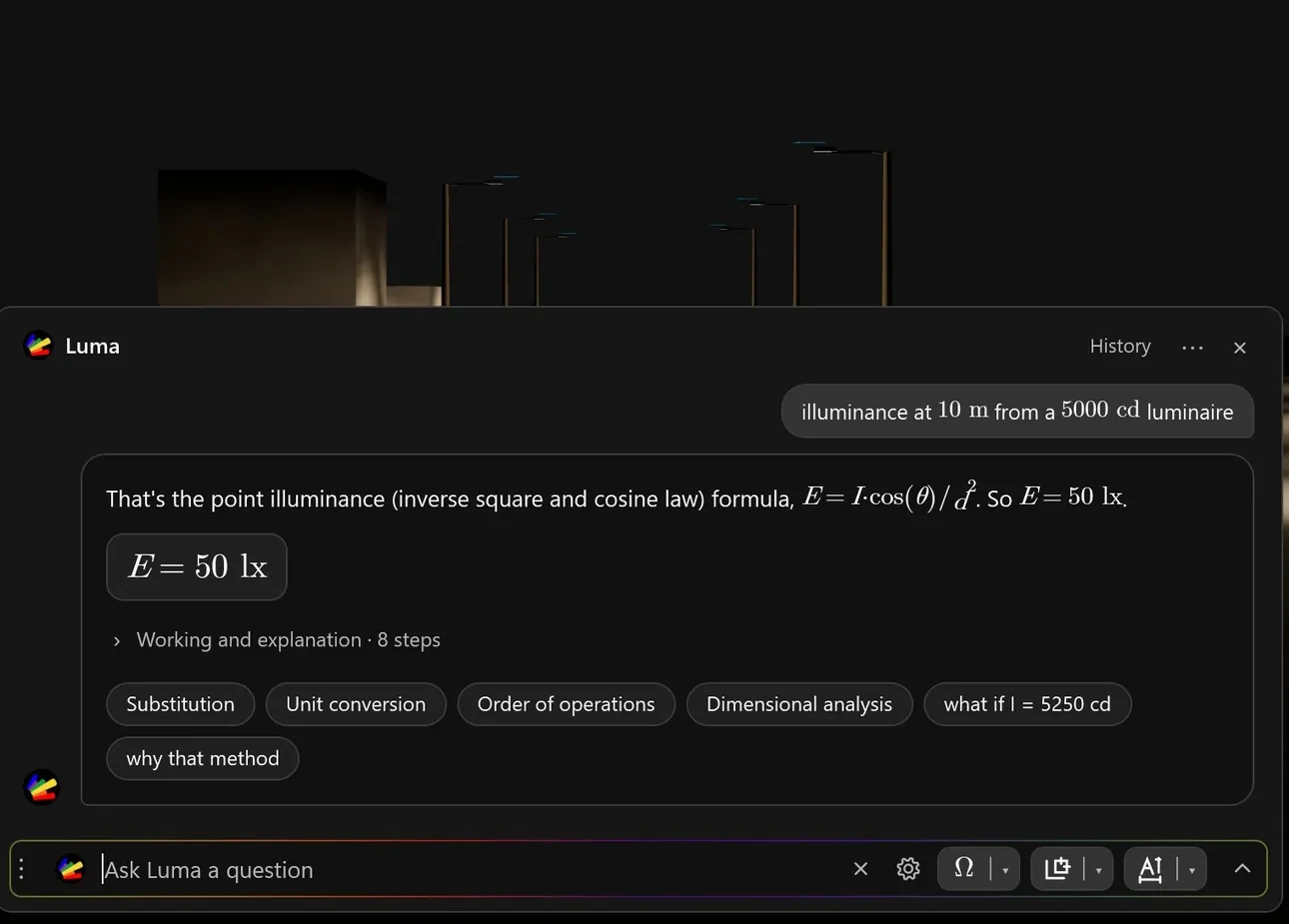
Lighting calculations in the command bar.
Type Luma and a question. Luma answers from the open project, the user manual and the calculation engine, with each result written as typeset mathematics and the working available.
- Worked answers with formula recognition, unit conversion and steps
- Inputs on request: when a formula needs values, Luma asks for each with its unit
- Project aware questions about the open project and its results
- Symbol library with every lighting formula as a template
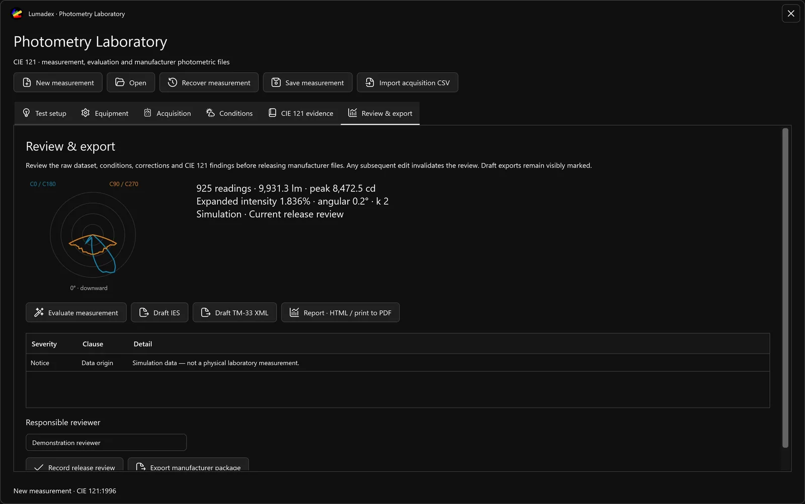
A measurement workflow structured around CIE 121.
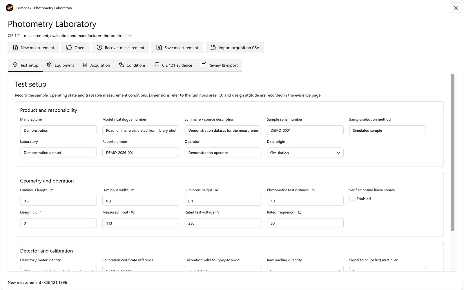
The laboratory takes a measurement from test setup to reviewed photometric files. Each step records what CIE 121 asks a laboratory to show. Any later edit invalidates the review.
- Test setup: product identity, geometry, supply and scan plan
- Equipment: meter and goniometer profiles over TCP, serial or a vendor SDK
- Conditions: stabilisation, return checks and the uncertainty budget
- Review: findings by clause, then draft IES or TM 33 export
A module for every Standard you design to.
Core road and pedestrian lighting is part of the base application. Specialist modules install as add ons and appear on the home screen once installed. Each states its calculation scope before you start.
Vehicular roads
Category V1 to V5 average luminance, Uo, UL, TI and SR from the luminaire photometry, with conflict areas, intersections and traffic calming devices to Section 4. Intersections and roundabouts are lit to the highest intersecting subcategory.
- Traffic calming devices from templates: road humps, chicanes, pedestrian refuges and raised islands
- Spacing studies search spacing, height and outreach
- Australian and New Zealand settings
Local roads and pathways
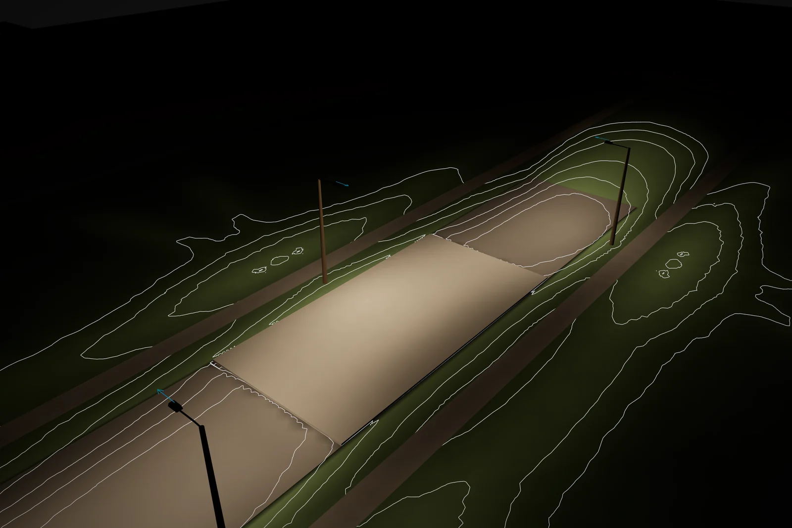
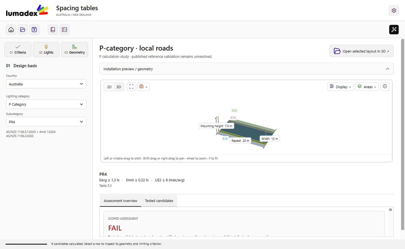
P category studies tabulate average and minimum illuminance, uniformity, vertical and surround illuminance for every tested spacing, to Tables 3.3 and 3.4. The S/P design multiplier is applied only from declared spectral evidence.
- PR1 to PR6 roads and PP1 to PP5 paths
- A passing row placed as poles in one step
- Public areas PA1 to PA3 and connecting elements PE1 to PE3
Car parks
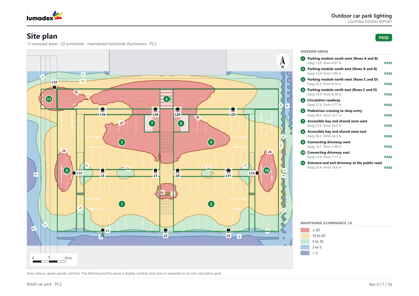
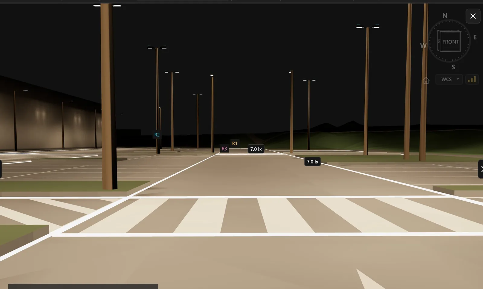
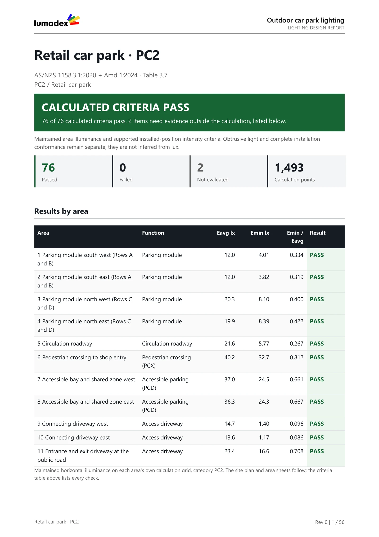
Parking modules, circulation roadways, accessible bays and pedestrian crossings are drawn as linked areas, each with its PC category and checked against the average of its relevant adjacent area.
- PC1 to PC3, PCD and PCX categories
- Opposing vertical planes at crossings
- Table 3.8 intensity limits kept open until flux evidence is attached
Pedestrian crossings
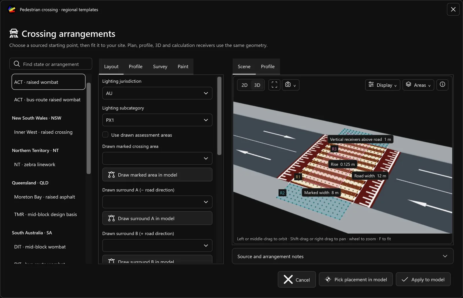
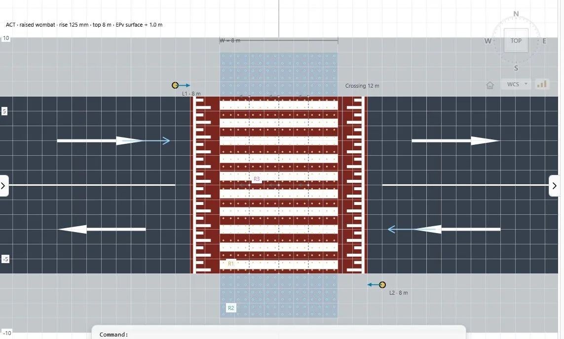
Arrangements sourced from Australian state and territory practice are fitted to the site. Plan, profile, 3D view and receivers share one geometry, with vertical receivers facing each direction of travel.
- PX1 and PX2 categories
- Regional templates from NSW, Queensland and Victoria
- Raised crossings with their profile
Bus stops
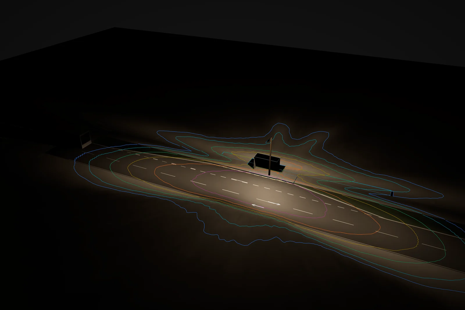
Boarding pads, shelters and approach areas are assessed with horizontal and vertical receivers facing the approaching bus. Sloped ground is supported.
- Directional boarding areas
- Approach fields on sloped sites
- Fly through with the bus into its stop
Rail level crossings
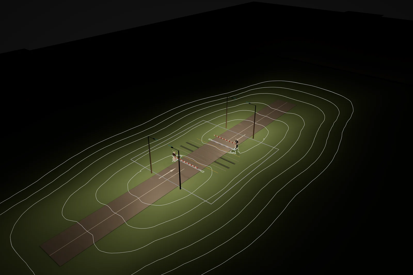
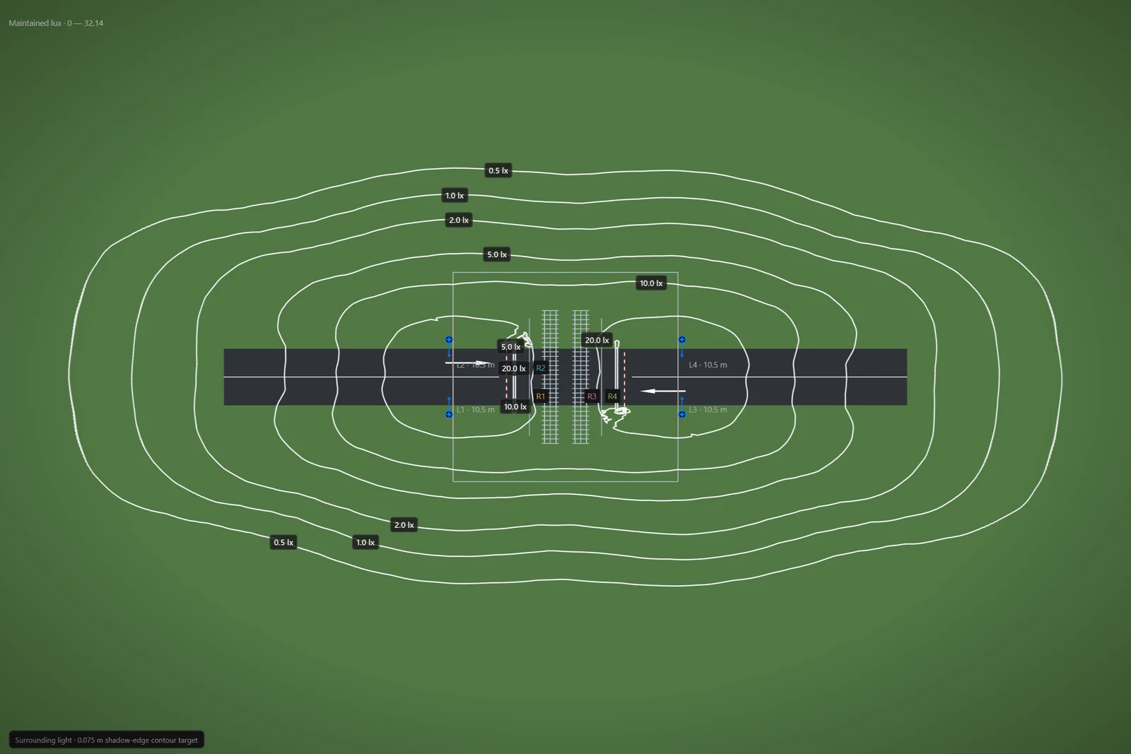
Average vertical illuminance on the plane of the furthest track facing each approach, with every column checked against the 10 m setback from the rail corridor.
- Crossings on the real curved alignment
- Train facing planes for each approach
- Warning lights and booms in the night view
Tunnels and underpasses
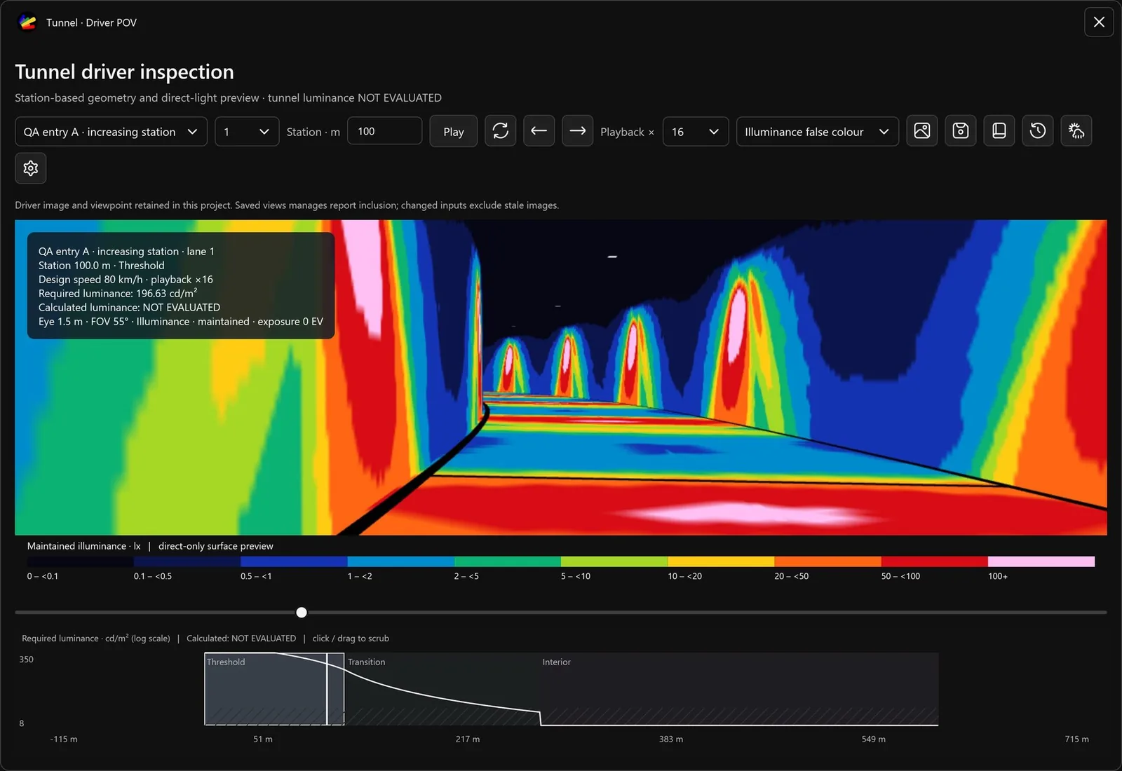
Zones run from the threshold through transition to the interior along the real alignment. Road and wall luminance, L20, threshold increment and lighting stages are assessed for each direction of travel. Underpasses are checked for visibility to Appendix D.
- Driver view at eye height with the zone requirement profile
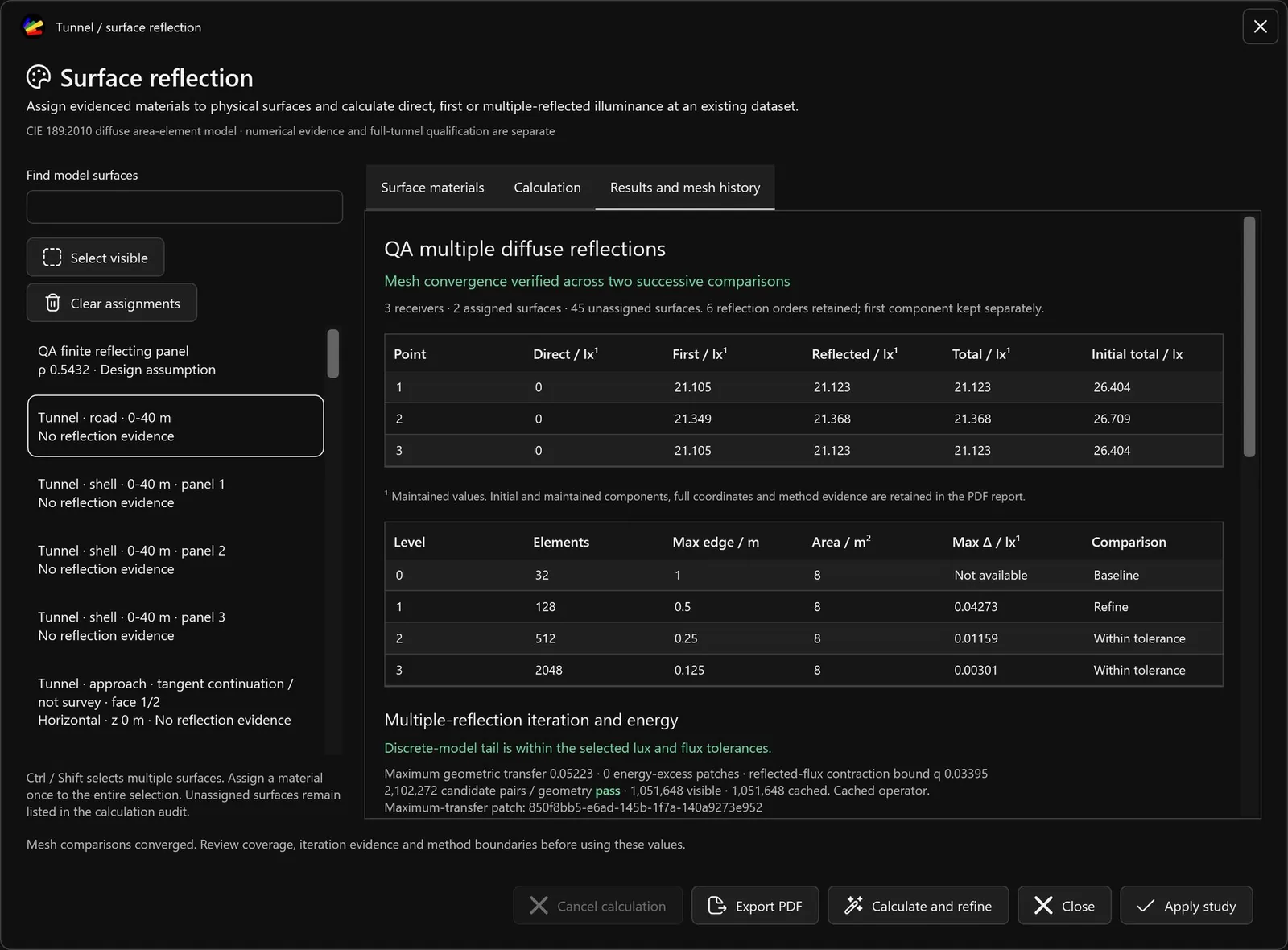
- First and multiple reflected light to CIE 189
- Every switching stage as its own field
Obtrusive light
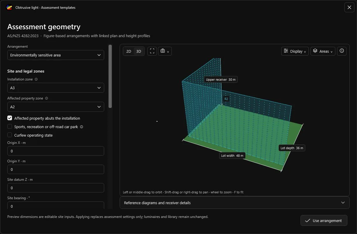
Figure based templates set up the site, the affected property and its receivers. Lumadex calculates vertical illuminance on each receiver plane and the luminous intensity toward it, by zone and curfew state.
- Boundary and window illuminance
- Source intensity and upward light ratio
- Reach volume around the property
Lighting near aerodromes
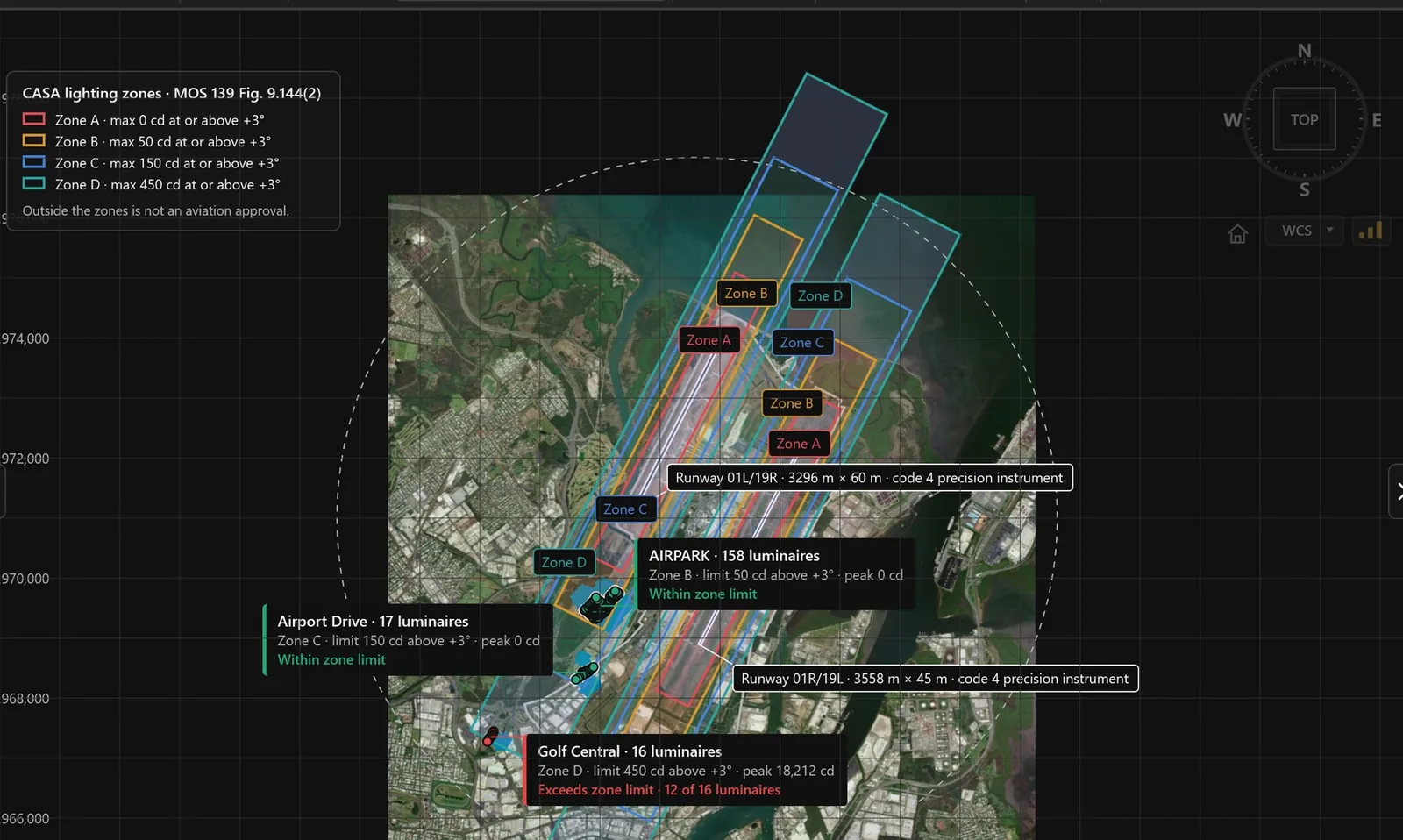
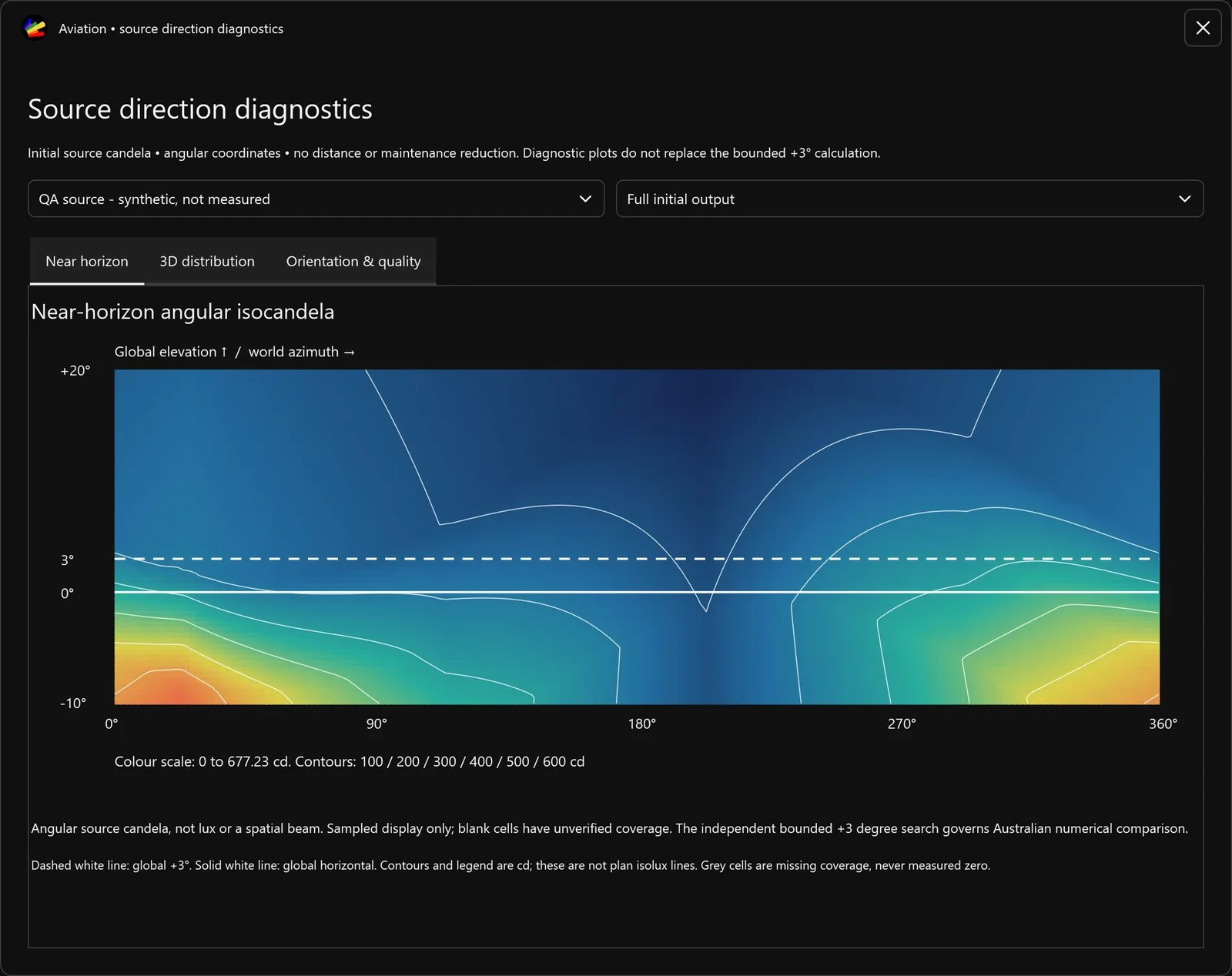
Lighting zones are built from the aerodrome reference point and the runway ends. Every luminaire's intensity above the horizon is searched against the limit of the zone it stands in, with a bounded search so peaks between measured angles are not missed.
- Zones A to D around the runways
- Near horizon diagnostics around the full azimuth
- A numerical comparison for review, not an aviation approval
Sports
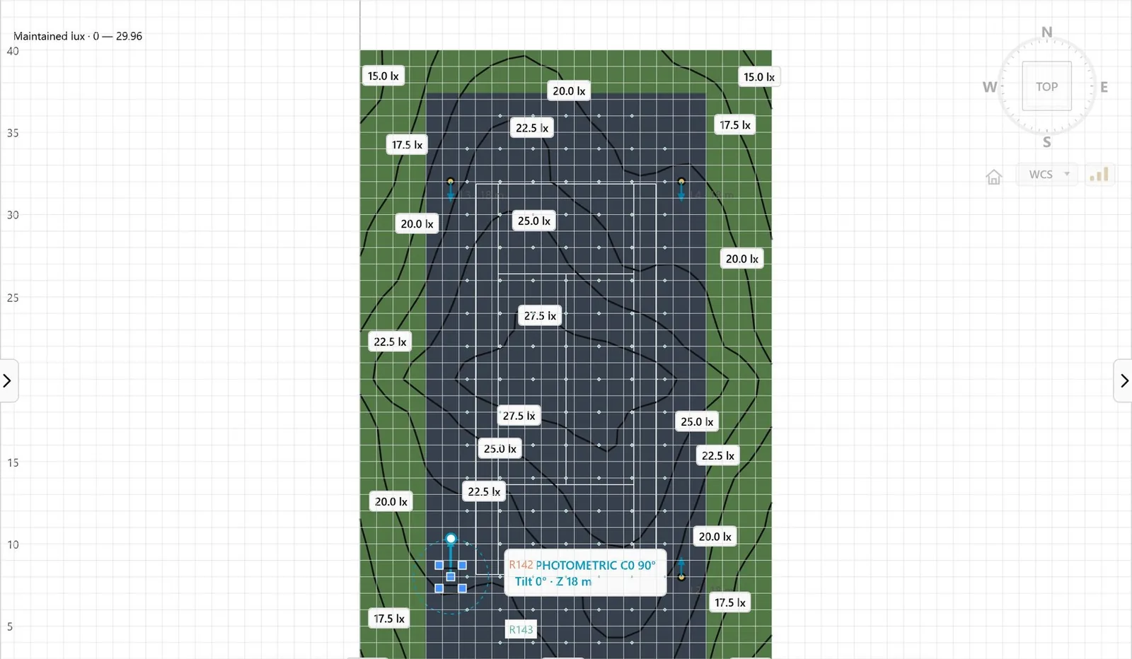
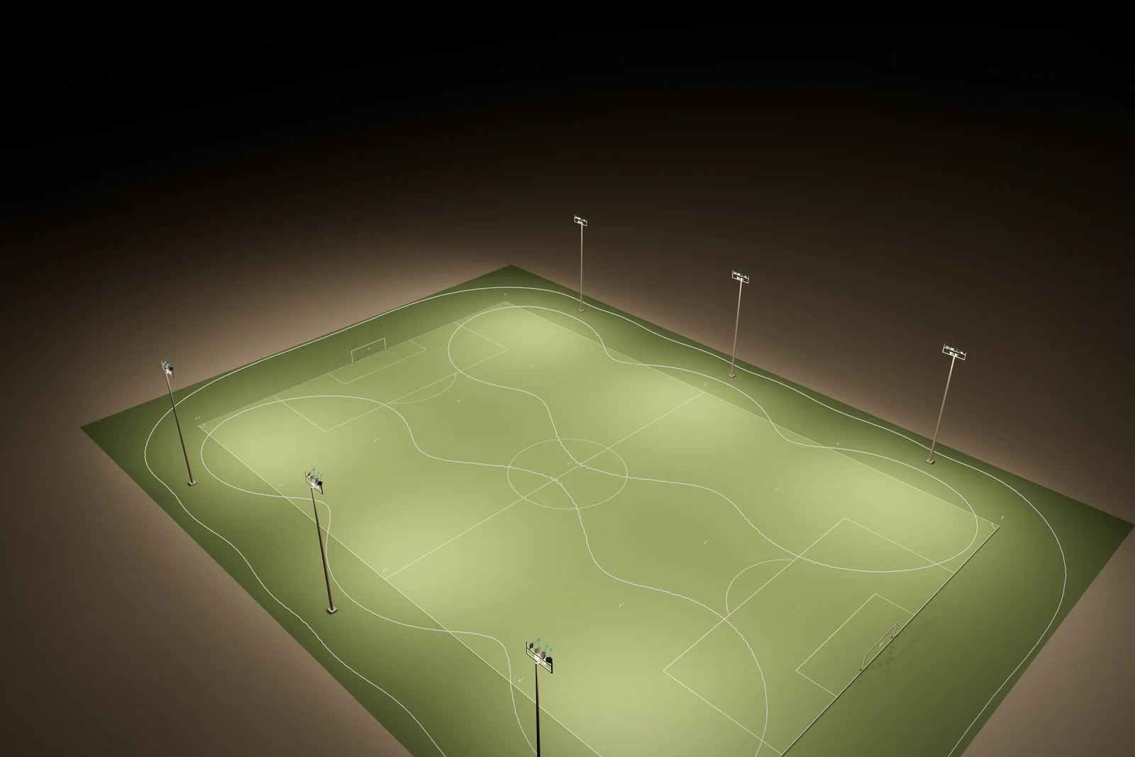
Sports studies set the sport, the competition level and the playing geometry, then generate the design grid. Results compare average horizontal illuminance and uniformity with the selected class.
- Courts placed on surveyed coordinates
- Sport specific design grids
- Criteria with the controlling location
Interior and workplace
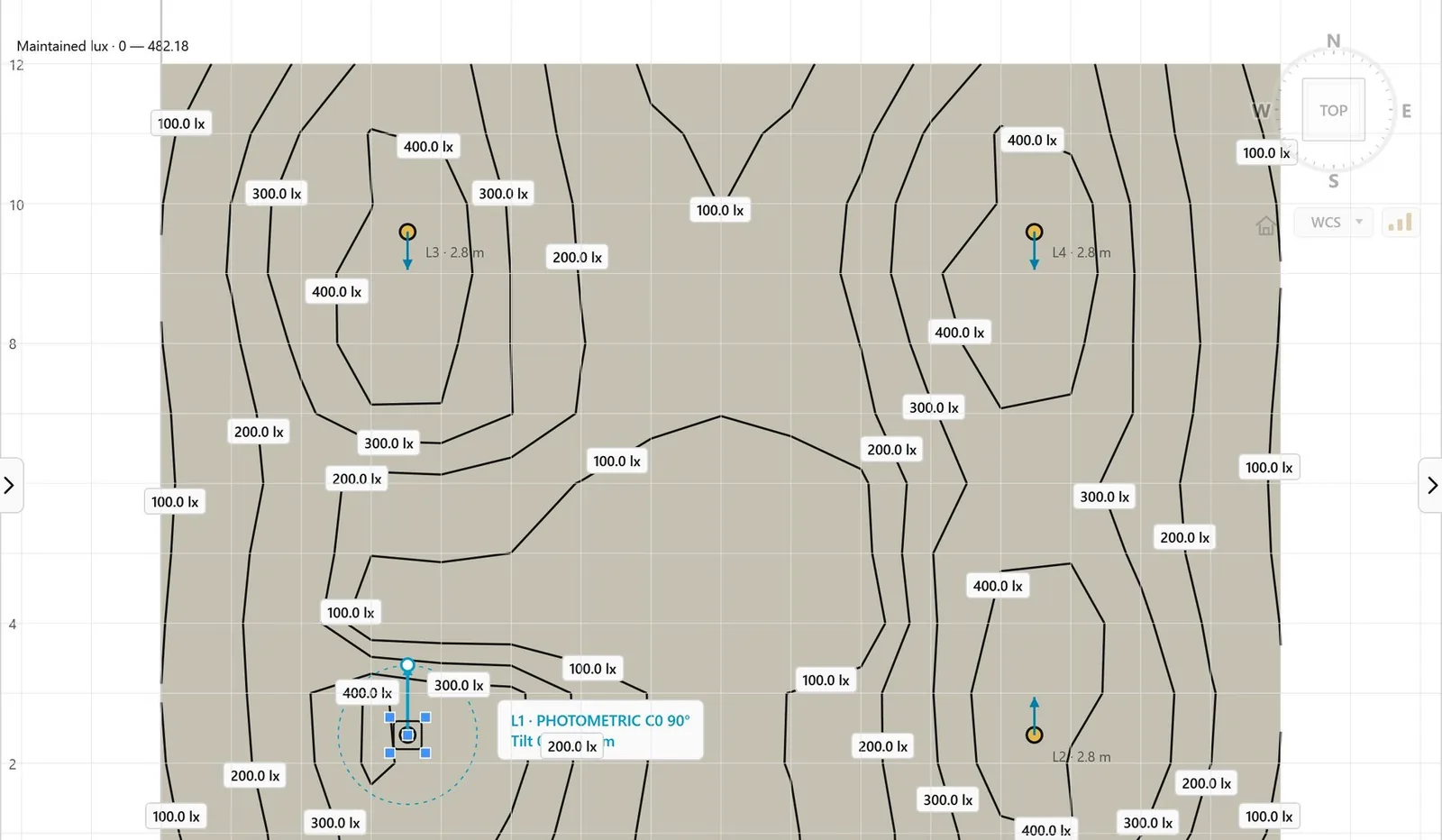
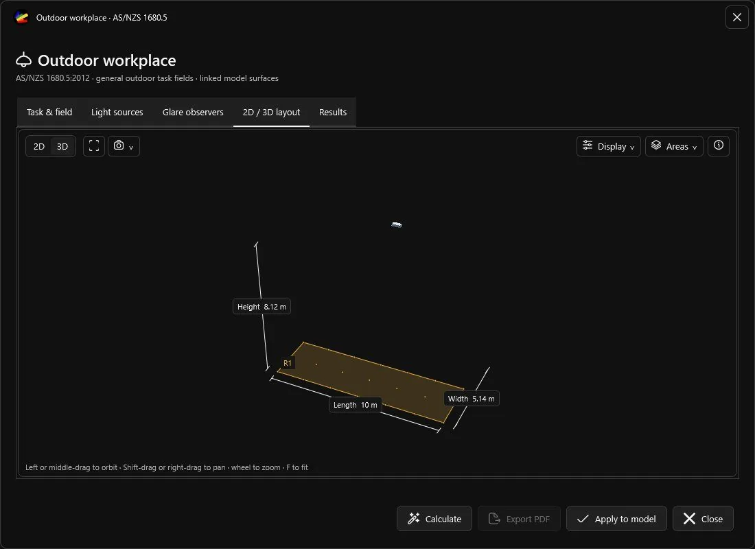
Task areas are linked to rooms and their criteria come from the selected table entry. Reflections off room surfaces use evidenced materials. Outdoor workplace tasks are assessed with glare observers.
- Maintained illuminance, uniformity, UGR and Ra
- Measured spectrum for each operating state
- Table 3.1 outdoor tasks with glare observers
Emergency lighting
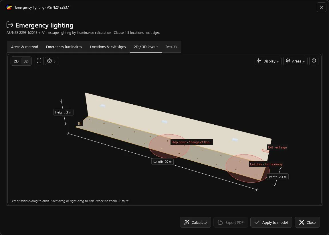
Escape routes are calculated by point illuminance using emergency mode photometry. Clause 4.5 locations, exit signs and their viewing distances are checked alongside floor illuminance.
- Escape routes and open areas
- Clause 4.5 locations
- Exit signs and viewing distances
Photometry Laboratory
The laboratory takes a measurement from test setup to reviewed photometric files, recording at each step what CIE 121 asks a laboratory to show.
- Meter and goniometer profiles
- Uncertainty budget and return checks
- Draft IES and TM 33 export after review
Lumadex for CAD
Place luminaires and draw assessment areas in CAD model space, calculate with the same engine and draw isolux contours, verdicts, tables, spacing and certificates into the drawing.
- Live results while you drag
- Spacing runs and Auto Calculate
- One project shared with Lumadex Desktop

What Lumadex assesses.
Each module carries the categories, tables and clauses of its Standard. Choose the category and Lumadex sets the targets, the calculation grid and the checks.
| Standard | Application | What is checked |
|---|---|---|
| AS/NZS 1158.1.1:2022 | Vehicular roads, Category V1 to V5 | Average luminance, Uo, UL, TI and SR from the luminaire photometry. Conflict areas, intersections, roundabouts and road devices to Section 4. |
| AS/NZS 1158.1.1:2022 Clause 4.6 | Railway level crossings | Average vertical illuminance on the plane of the furthest track facing each approach, with the 10 m column setback. |
| AS/NZS 1158.3.1:2020 + Amd 1:2024 | Local roads PR1 to PR6, paths PP1 to PP5 | Tables 3.3 and 3.4: average and point illuminance, uniformity, vertical and surround illuminance, S/P design multiplier. |
| AS/NZS 1158.3.1 Table 3.7 | Car parks PC1 to PC3, PCD and PCX | Each area against its category and its adjacent area, opposing vertical planes, Table 3.8 intensity limits. |
| AS/NZS 1158.3.1 | Public areas and connecting elements | PA1 to PA3 and PE1 to PE3: stairs, ramps, bridges and subways. |
| AS/NZS 1158.4:2024 | Pedestrian crossings PX1 and PX2 | Crossing and surround illuminance, vertical illuminance facing each direction of travel. |
| AS/NZS 1158.5:2014 | Tunnels and underpasses | Threshold, transition and interior luminance, L20, threshold increment, walls and lighting stages. |
| AS/NZS 4282:2023 | Obtrusive light | Illuminance at property boundaries and windows, source intensity, upward light. |
| AS/NZS 2293.1:2018 | Emergency escape lighting | Escape routes and open areas, Clause 4.5 locations, exit signs. |
| AS/NZS 1680 series | Interior and outdoor workplaces | Task and surround illuminance, uniformity and glare. |
| AS 2560 series | Sports lighting | Sport specific design grids, illuminance and uniformity. |
| CASA Part 139 MOS | Lighting near aerodromes | Intensity above the horizon against the limit of each lighting zone. |
| CIE 121 | Photometry laboratory | Test setup, equipment, acquisition, conditions, uncertainty and review before export. |

Every criterion, with its evidence.
Every criterion is reported with its clause, the required value, the calculated value and the location that controls it. Values are compared at the precision the Standard prints. A criterion without the evidence it needs is shown as incomplete, never as a pass.
Your Standards stay yours.
Lumadex carries the categories, values and clause references it needs to calculate and report. It does not embed or reproduce the text of any Standard. Keep your licensed copies to hand for the wording.
Design in XeraCAD, AutoCAD, BricsCAD, AutoCAD LT and BricsCAD Lite.
The Lumadex module places luminaires from the Lumadex library and draws assessment areas in model space. It calculates with the same engine and draws the results into the drawing. The DWG carries the Lumadex data between all five programs.
Assessment where you draft.
Every program carries the full drawing workflow below: the same Lumadex pane, ribbon, commands and licence with one project shared with Lumadex Desktop.
Library and placement
Choose a luminaire from your Lumadex library, set its mounting, then place one, along a path or on a shared pole. Blocks show the pole, arm and head in plan and in 3D.
Live results while you drag
Move a luminaire and the isolux, area verdicts, tints and spacing follow the cursor before you release, in the drawing's own font and layout.
Results in the drawing
Whole isolux contours with masked labels, verdicts and values, area tints with calculation points, results and schedule tables.
Spacing runs
The line of sight between poles with its distance, coloured within S or over. Runs pair poles from where they stand.
Auto Calculate
Hatched Auto Calculation areas in hazard tape or your own colours. Auto moves, turns and tilts the poles inside them and keeps every spacing run within S.
Certificates
Lighting certificates of compliance for areas or a maximum spacing study. Flag and hazard lighting certificates too. All inserted as blocks.
The drawing and Lumadex Desktop stay in step.
The drawing writes a Lumadex project beside it. Open it in Lumadex Desktop for terrain, night views, specialist modules and reports. Import a Lumadex project back into the drawing with every identity kept.
- Luminaires and areas with their tags and identities
- Each drawn pole and arm, so Desktop draws and measures from the same pole
- Spacing runs and Auto Calculation areas, edited in either program
- Mirror safety: content the drawing no longer supports is reset with a message, never silently
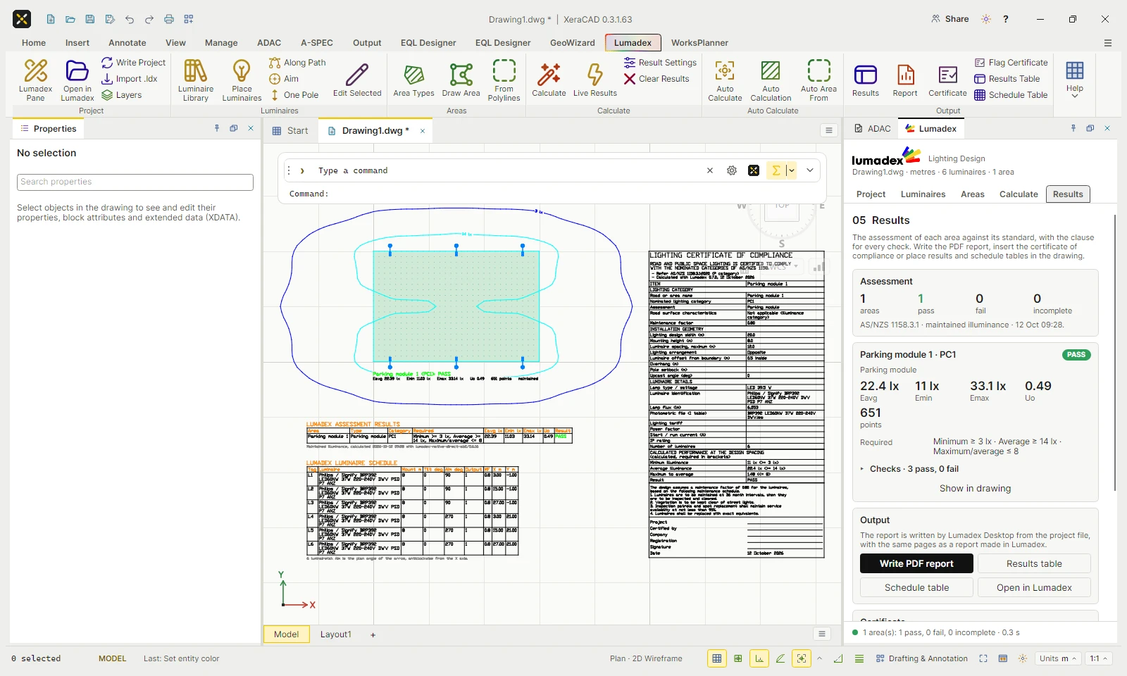
Five programs, one engine.
Lumadex for XeraCAD
A Start page module card, the Lumadex ribbon tab and pane, live preview while dragging, spacing runs, Auto Calculate and certificates.
Lumadex for AutoCAD
The Lumadex palette docked beside the drawing, the Lumadex ribbon tab, live results while you drag, spacing runs, Auto Calculate, certificates and the ldx: LISP functions. AutoCAD 2025 and 2026.
Lumadex for BricsCAD
The same pane, ribbon and workflow in BricsCAD V26 Pro and Platinum, with the Lumadex data carried in the DWG between every program.
Lumadex for AutoCAD LT and BricsCAD Lite
Every Lumadex command, the pane in its own window, the ribbon tab, the licence check and the link to Lumadex Desktop, through AutoLISP and the Lumadex CAD companion. AutoCAD LT 2024 or later and BricsCAD V26 Lite.
Set up from Lumadex. At home in XeraCAD.
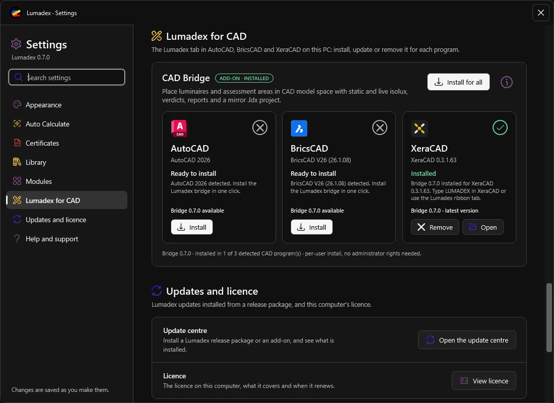
Lumadex Settings lists every CAD program on the computer with its version and whether the Lumadex tab is installed, ready or needs a restart. One click adds or removes it. Lumadex Setup offers the same choice when it installs.
- Lumadex in XeraCAD Options (LDXOPTIONS): defaults for new luminaires and areas and how results are drawn, with a live preview
- The user manual offline with the module: LDXHELP, F1 in the pane or the User Manual button
- One licence: the module uses the licence Lumadex Desktop holds, signed and checked offline
- Ribbon icons in colour, each command family in its own part of the spectrum
See Lumadex on one of your own sites.
We would welcome the chance to take your team through Lumadex against the Standards you design to. Draw the area and see the first calculation before the survey arrives.